


Views: 0 Author: Site Editor Publish Time: 2026-07-24 Origin: Site


The foundation of a vehicle’s handling, load capacity, and ride quality rests entirely on its suspension geometry, with the Coil Spring acting as the primary load-bearing component. These coiled lengths of steel dictate how a chassis reacts to road imperfections, weight transfer during cornering, and the addition of heavy cargo. Selecting an incorrect spring—whether mismatching the spring rate, choosing the wrong design type, or ignoring suspension motion ratios—results in compromised vehicle dynamics, accelerated shock wear, and unsafe handling under load. Understanding the mechanical differences between various spring designs is essential for achieving the desired ride characteristics. A technical evaluation framework allows drivers and technicians to compare designs, calculate appropriate spring rates, and match suspension components to specific operational requirements. Whether the vehicle is built for daily street driving, competitive track use, rugged off-road trails, or heavy towing, the right suspension setup begins with accurate spring selection.
A properly specified suspension spring achieves specific mechanical objectives that keep a vehicle safe and controllable. When a vehicle hits a bump, the spring compresses to absorb the upward force, preventing that kinetic energy from transferring directly into the chassis. The shock absorber then controls the release of that stored energy. Without the correct spring rate, the suspension either bottoms out over minor impacts or remains too rigid to articulate properly.
To evaluate a suspension setup, technicians look at three primary success criteria:
There is an inherent inverse relationship between high load capacity and passenger comfort. Stiffer springs are necessary to support heavy payloads, reduce body roll, and maintain stability at high speeds. However, this stiffness directly transmits more road vibration into the cabin. Drivers must evaluate their subjective preferences regarding ride feel. Softer springs provide a highly insulated, comfortable ride suitable for daily commuting, while stiff performance springs deliver high-feedback, firm dynamics necessary for precise steering inputs on a track.
Understanding the concept of wheel rate is critical when evaluating suspension dynamics. The physical location of the spring on the control arm means the effective wheel rate is almost always lower than the raw spring rate. Because the spring is usually mounted inboard from the wheel hub, it operates at a mechanical disadvantage. The wheel acts as a lever against the spring. Therefore, a 500 lbs/in spring mounted halfway down a control arm will yield a significantly lower actual wheel rate, requiring careful calculation to ensure the suspension performs as intended. If you ignore the motion ratio, you will end up with a suspension that is far too soft for your intended application.
Suspension frequency is another metric used to determine ride quality. Measured in Hertz (Hz), it describes how fast the suspension oscillates after hitting a bump. Passenger cars typically aim for a suspension frequency between 1.0 and 1.5 Hz for maximum comfort. Sports cars push this to 1.5 to 2.0 Hz for better body control, while dedicated race cars with high downforce might exceed 2.5 Hz. The spring rate directly dictates this frequency based on the vehicle's sprung mass.
The physical winding of the steel wire determines how the spring behaves under compression. Manufacturers utilize different winding techniques to achieve specific handling characteristics tailored to different driving environments. Selecting the wrong winding type will fundamentally alter how the vehicle responds to weight transfer.
Linear springs feature a consistent distance between each coil and compress at a uniform rate throughout their entire stroke. If a linear spring is rated at 300 lbs/in, it takes exactly 300 pounds of force to compress it one inch, 600 pounds to compress it two inches, and so forth. This uniform behavior makes them highly predictable. They are the standard choice for track vehicles, heavy-duty towing, and applications requiring absolute consistency in weight transfer during aggressive cornering or braking.
Progressive springs are engineered with variable spacing between the coils or by tapering the wire diameter. As the spring compresses, the closer coils bind together, effectively reducing the number of active coils and increasing the spring rate. This means the spring is soft during initial compression to absorb small road bumps but becomes progressively stiffer to prevent bottoming out over large impacts. They are ideal for daily driven vehicles, street-performance cars, and varied terrain where initial compliance and secondary bottom-out resistance are required.
Dual-rate setups utilize two distinct linear rates stacked on top of one another, often utilizing a softer tender spring and a stiffer main spring separated by a mechanical slider. The tender spring absorbs minor impacts and keeps the main spring seated during full suspension droop. Once the tender spring fully compresses (binds), the system transitions entirely to the stiffer rate of the main spring. This architecture is best suited for long-travel off-road suspensions and specialized coilover setups requiring massive droop travel.
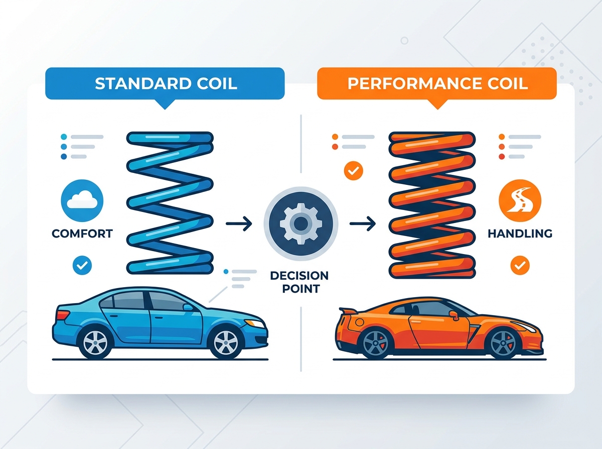
Matching the spring design to the vehicle's primary use case prevents premature wear and dangerous handling characteristics. Different driving environments demand entirely different suspension geometries. A setup that works flawlessly on a smooth racetrack will be undrivable on a rocky off-road trail.
When replacing worn factory components, the focus remains on matching the original spring rates, wire diameter, and free length to restore factory geometry. Technicians must account for subtle variations in vehicle trim levels. Engine displacement, drivetrain configurations (AWD versus FWD or RWD), and transmission types (automatic versus manual) directly alter the front-axle curb weight. A spring designed for a lightweight four-cylinder manual vehicle will sag significantly if installed on a V6 automatic model. Diagnostics should include identifying signs of existing fatigue, such as sagging ride height, heavy surface corrosion, or micro-fracturing along the lower coils.
Track-focused applications require increasing the spring rate to reduce body roll, pitch under braking, and squat under acceleration. Lowering the center of gravity is a primary objective, which inherently reduces available suspension travel, necessitating stiffer springs to prevent the chassis from striking the bump stops. Variables such as corner-balancing, unsprung weight reduction, and tire compound grip limits must be factored into the selection. High-grip tires generate more lateral force, requiring stiffer springs to maintain optimal camber angles during hard cornering.
Off-road and towing applications prioritize increasing load capacity and maximizing suspension articulation. Upgraded springs must compensate for added static weight from aftermarket steel bumpers, heavy-duty winches, roof racks, or trailer tongue weight. The challenge lies in increasing the load capacity without causing coil bind at full compression or making the unladen ride unbearably harsh. Extended free-length springs are often utilized to increase static ride height while maintaining adequate downward travel.
| Application | Preferred Spring Type | Primary Objective | Ride Quality Impact |
|---|---|---|---|
| OEM Street Driving | Progressive | Restore factory geometry and comfort | Soft, compliant, insulated |
| Track / Autocross | Linear | Reduce body roll, maximize grip | Firm, high feedback, harsh on bumps |
| Off-Road / Overlanding | Dual-Rate / Linear | Maximize articulation, support heavy gear | Variable, depends on shock valving |
| Heavy Towing | Linear (High Rate) | Prevent rear-end sag under load | Very stiff when unladen |
Selecting the correct hardware requires moving beyond subjective feel and utilizing mathematical formulas to ensure the suspension operates within its designed parameters. Guessing spring rates based on forum recommendations often leads to poor handling and wasted money.
A formulaic approach is necessary to determine the optimal spring rate. This involves factoring in the vehicle's sprung weight (the weight supported by the suspension), the specific corner weight, the suspension motion ratio, and the desired suspension frequency. The motion ratio squared is multiplied by the desired wheel rate to find the required spring rate. Demystifying the units of measurement is also crucial. Imperial measurements use pounds per inch (lbs/in), while metric systems use kilograms per millimeter (kg/mm) or Newtons per millimeter (N/mm). Converting kg/mm to lbs/in requires multiplying by approximately 56.
To calculate the required spring rate, you must first determine the motion ratio. Measure the distance from the inner control arm pivot to the center of the spring mount. Then measure the distance from the inner pivot to the center of the ball joint. Divide the first number by the second number. Square this result. Divide your target wheel rate by this squared motion ratio to find your required spring rate.
The free length is the uncompressed, resting length of the spring. The compressed length, or block height, is the height of the spring when all coils are touching and no further compression is possible. Evaluating both dimensions is critical to prevent coil bind. If a spring reaches its block height before the suspension reaches its bump stop, the suspension will instantly become rigid, transferring massive, destructive force into the shock mounts and chassis.
Vehicles utilize different suspension architectures. Integrated coilover shocks package the spring directly over the damper body, offering compact packaging and straightforward ride height adjustability via threaded collars. Divorced setups, common in rear suspensions, separate the spring and the shock absorber. Coilovers generally offer a 1:1 or near 1:1 motion ratio on MacPherson strut designs, while divorced setups rely heavily on control arm leverage, requiring drastically different spring rates to achieve the same wheel rate.
Installing new springs without considering the rest of the suspension system introduces severe drivability issues and mechanical risks. A spring is only one half of the damping equation; the shock absorber is the other.
Pairing a high-rate performance spring with an OEM shock absorber leads to an under-damped, bouncy ride. Factory shocks are valved to control the rebound energy of factory-rate springs. When a stiffer spring compresses and releases, the factory shock lacks the damping force to slow the spring's extension, causing the vehicle to oscillate rapidly after hitting a bump. The mitigation strategy requires re-valving existing shocks or purchasing matched damper and spring combinations engineered to work together.
Clearance and coil bind issues present significant mechanical hazards. Selecting a spring with an incorrect block height causes the coils to crash into each other before the suspension reaches the bump stop. This acts as a solid steel block, destroying shock internals and potentially tearing shock mounts from the chassis. Calculating maximum suspension travel and verifying spring block height specifications prior to installation eliminates this risk.
Altering ride height via shorter or taller springs fundamentally changes the vehicle's suspension geometry, impacting camber, caster, and toe angles. Lowering a vehicle often induces excessive negative camber, leading to accelerated inner tire wear and reduced straight-line braking grip. Mandating a professional alignment immediately after installation is non-negotiable. In many cases, installing adjustable control arms, camber bolts, or camber plates is necessary to bring the alignment back within safe, drivable specifications.
A: Spring rate is the amount of force required to compress the spring itself by one inch. Wheel rate is the actual force required to move the wheel assembly one inch. Because springs are usually mounted inboard on control arms, leverage reduces the effective force, making the wheel rate lower than the spring rate.
A: Signs of fatigue include a noticeable drop in static ride height, uneven tire wear, frequent bottoming out over minor bumps, and visible physical damage such as heavy rust, pitting, or micro-fractures on the steel coils.
A: It is highly discouraged. Stock shocks are valved for factory spring rates. Installing stiffer springs overwhelms the shock's rebound damping, resulting in an under-damped, bouncy ride that compromises vehicle stability and accelerates shock failure.
A: Coil bind occurs when a spring compresses completely, causing all the coils to touch and form a solid cylinder. This prevents further suspension travel and causes severe damage. Prevent it by ensuring the spring's block height is shorter than the suspension's maximum compressed length.
A: Often, they do not. Automatic transmissions are generally heavier than manual transmissions. This extra weight over the front axle requires a slightly stiffer spring rate or a taller free length to maintain the correct factory ride height.
A: To convert pounds per inch (lbs/in) to kilograms per millimeter (kg/mm), divide the lbs/in value by 56. For example, a 500 lbs/in spring is approximately equal to an 8.9 kg/mm spring. To convert kg/mm to lbs/in, multiply by 56.


