


Views: 0 Author: Site Editor Publish Time: 2026-07-25 Origin: Site


A Coil Spring serves as a foundational mechanical device constructed from tightly wound helical metal wire, engineered specifically to store energy, absorb shock, and maintain consistent force between contacting surfaces. Mechanical reliability in dynamic systems fundamentally relies on this precise energy storage and controlled force distribution. When engineers or technicians specify the wrong spring for an application, they introduce severe operational risks. Improper spring specification directly leads to premature fatigue failure, compromised structural integrity, unexpected system downtime, and significant safety hazards in both automotive suspensions and heavy industrial machinery.
This technical guide moves past basic definitions to establish a rigorous framework for evaluating, specifying, and sourcing the correct mechanical components. We will examine how to accurately assess dynamic load requirements, navigate harsh environmental constraints, and meet strict lifecycle expectations. By understanding the core mechanics, material properties, and failure modes, you can ensure optimal mechanical performance and prevent catastrophic equipment failures in the field.
A tightly wound helical coil of metal absorbs mechanical energy upon deformation. When you compress, extend, or rotate the spring, the wire itself undergoes torsional or bending stress. The material stores this kinetic energy within its molecular structure. Once the external force is removed, the metal seeks to return to its original free length, releasing the stored energy. This fundamental physics principle allows springs to act as reliable mechanical buffers in high-stress environments, from heavy earth-moving equipment to precision aerospace actuators. The efficiency of this energy transfer depends heavily on the wire diameter and the specific alloy used during manufacturing.
In field applications, we see this energy storage capacity tested constantly. A suspension system hitting a pothole forces the spring to absorb massive kinetic energy in milliseconds. The spring must then release that energy at a controlled rate, usually managed by a damper, to keep the tire in contact with the ground. Without this rapid energy absorption and release, the rigid chassis would absorb the impact, leading to cracked welds and bent frames.
The operation of these components relies heavily on Hooke’s Law, which defines the linear relationship between the force applied and the distance of deformation (F = kx). The spring rate, or stiffness (k), dictates how much force is required to compress or extend the spring by one unit of measurement, typically expressed in pounds per inch (lbs/in) or Newtons per millimeter (N/mm). Calculating the exact spring rate is the foundational metric for any technical evaluation.
If the spring rate is too low, the system bottoms out under load, causing metal-on-metal contact. If the rate is too high, the system transfers excessive shock to surrounding components, defeating the purpose of the suspension or isolation mount. Engineers must calculate the exact load requirements and specify a spring rate that keeps the mechanism operating within its optimal travel range.
Not all coils in a spring contribute to its flexibility. Active coils are the turns of wire that actually deflect under load. Inactive coils sit at the ends of the spring and provide a flat, stable surface for seating against mounting hardware. The number of active coils directly impacts the spring rate and overall travel.
Fewer active coils result in a stiffer spring, while more active coils yield a softer rate, assuming wire diameter and outside diameter remain constant. When inspecting a spring in the field, counting the active coils helps verify if the correct part was installed. Dead coils at the end are usually ground flat to ensure they sit perfectly square in their perches, preventing the spring from bowing or buckling under heavy compression.
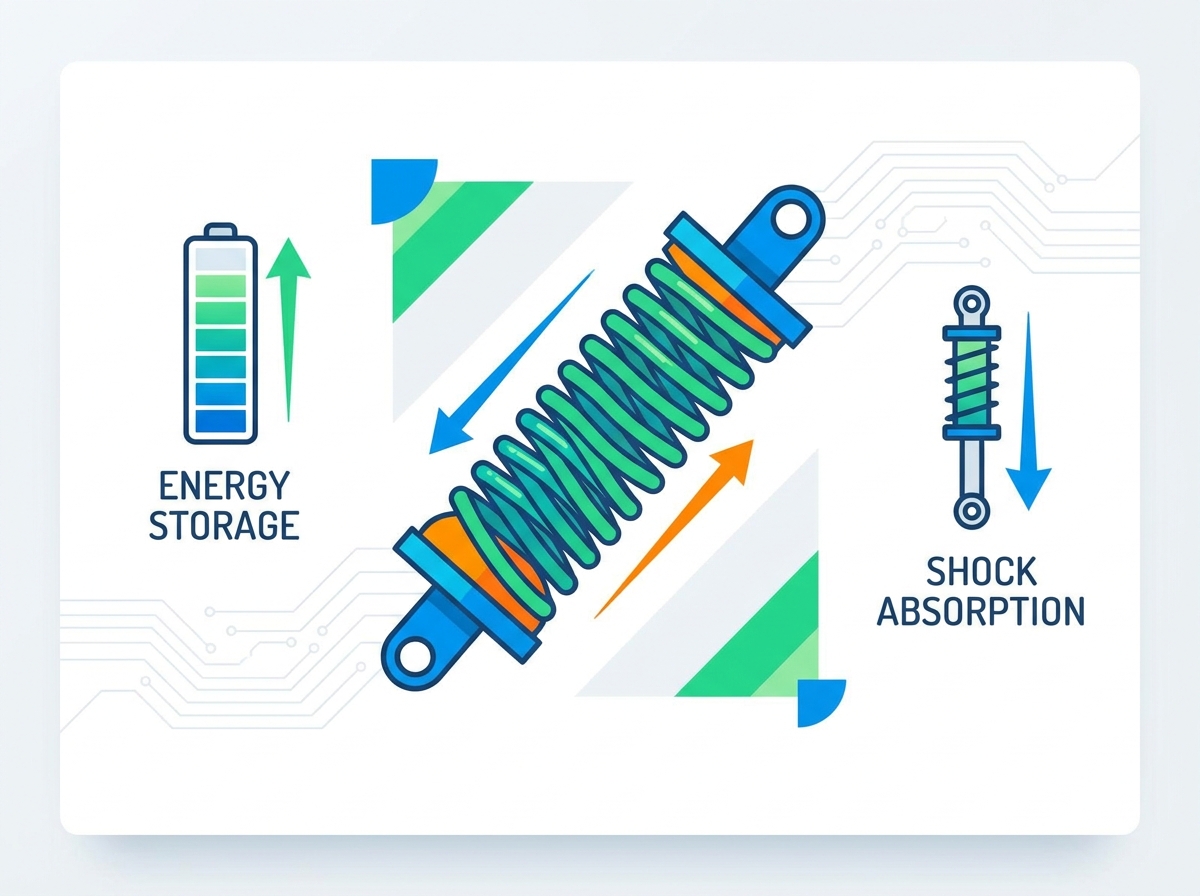
In vehicle suspensions and industrial machinery, springs dampen kinetic energy. They isolate the frame, chassis, or sensitive internal components from road impacts and transient structural forces. When a wheel strikes an obstacle, the spring compresses rapidly, absorbing the upward force and preventing that shock from transferring rigidly into the chassis. This isolation is critical for protecting sensitive electronics, maintaining operator comfort, and preventing structural fatigue in the equipment frame.
Industrial stamping presses and heavy vibratory screens rely on massive isolation springs to prevent the machine's violent kinetic energy from destroying the concrete foundation of the facility. These springs must absorb thousands of pounds of force repeatedly without suffering from metal fatigue.
Springs support both static and dynamic loads. In automotive systems, they maintain the designed ride height, keeping the vehicle level under the weight of the engine, passengers, and cargo. Proper load support prevents mechanical bottoming-out, where suspension components crash into each other, causing catastrophic damage.
Proper tension stabilizes vehicle steering geometry and ensures uniform wheel alignment. When a spring sags or fails, the suspension geometry shifts. This misalignment causes accelerated wear on auxiliary components like dampers, control arm bushings, and tires. Maintaining the correct ride height ensures that all suspension angles operate within factory specifications.
In industrial automation, springs maintain the alignment of guide rails and actuator arms. If a return spring loses its tension, the mechanism may not fully reset, causing the next cycle to jam or misalign, leading to ruined product and machine downtime.
Springs facilitate controlled, repeatable movement in valves, switches, and automated assemblies. They provide consistent return forces that reset mechanisms after actuation. Engine valve springs, for example, must close the intake and exhaust valves thousands of times per minute with absolute precision to prevent engine failure.
If a valve spring lacks the necessary tension, valve float occurs at high RPMs. The valve fails to close fast enough, and the piston strikes it, destroying the engine. This highlights why precise spring specification is non-negotiable in high-speed mechanical systems.
Designed to resist compressive forces applied axially, these are the most common type of spring. They push back against a load to maintain separation between components. You will find them in everything from ballpoint pens to heavy-duty mining truck suspensions.
| Design Variation | Geometry Characteristics | Primary Application Benefit |
|---|---|---|
| Standard Cylindrical | Constant diameter from end to end | Predictable linear rate, easy to manufacture |
| Conical | Tapered diameter, cone shape | Telescopes into itself for very low solid height |
| Barrel | Wider in the middle, narrow at ends | Resists buckling under heavy loads |
| Hourglass | Narrow in the middle, wider at ends | Provides progressive spring rate, self-centering |
Engineers must evaluate solid height limitations, which is the height when all coils touch. They must also assess buckling risks based on the slenderness ratio. If a compression spring is too long relative to its diameter, it will bow outward rather than compress straight down. End configurations, such as closed and ground, closed and unground, or open, dictate how the spring seats against its mounting surface.
These components absorb and store energy by creating resistance to a pulling force. They stretch to operate and pull components back together. Common applications include garage door mechanisms, trampoline springs, and return levers on heavy machinery.
Evaluation criteria for extension springs include initial tension requirements, which dictate how much force is needed just to separate the coils before the spring actually begins to stretch. Hook and loop configurations introduce significant stress concentrations. Machine loops, crossover loops, and side loops are common, but the bend where the loop meets the coil is almost always the point of failure. Engineers must carefully evaluate these stress points to prevent safety-critical failure.
Torsion springs resist rotational forces, known as torque, and store angular energy. They twist rather than compress or stretch. You see these in clipboards, mousetraps, and heavy-duty ramp doors on trailers.
Specification requires defining the leg configuration to ensure it mates properly with the actuating mechanism. Engineers must ensure adequate mandrel clearance during wind-up, because the inside diameter of a torsion spring shrinks as it twists. If it binds on the mounting shaft, it will snap. Selecting the correct direction of wind, left-hand versus right-hand, is critical to match the application's rotational direction.
Springs offer high energy storage capacity, but this must be balanced against the physical footprint required. The free length, outside diameter, and wire diameter dictate how much space the component consumes. Engineers frequently face trade-offs between maximizing travel and fitting the spring into a confined housing.
In compact hydraulic valves, space is severely limited. You need a spring strong enough to resist high fluid pressure, but small enough to fit inside a machined bore. This often requires using specialized high-tensile wire that can handle higher stresses without taking a permanent set, allowing for a smaller overall spring footprint.
Material selection heavily influences weight and lifespan. Heavy-duty steel alloys provide high fatigue life but add significant weight to the assembly. Advanced materials like titanium or composites offer low weight and high performance for aerospace or performance automotive use, but they introduce high manufacturing costs and complex machining requirements.
In racing applications, reducing unsprung weight is critical for suspension performance. Swapping heavy steel springs for titanium equivalents drastically improves wheel control over rough surfaces, but the procurement team must justify the massive increase in component cost.
Standard linear springs provide a constant force throughout their travel. If it takes 100 pounds to compress the first inch, it takes another 100 pounds to compress the second inch. Progressive springs, utilizing variable pitch or varying wire diameters, offer increasing resistance as they compress.
Progressive designs excel in dynamic, unpredictable load environments. They provide a soft initial response over small bumps, maintaining traction and comfort. As the suspension compresses further under heavy impacts, the spring stiffens rapidly to prevent the chassis from bottoming out. This dual-nature performance makes progressive springs ideal for off-road vehicles and heavy payload trucks.
Successful specification begins with establishing baseline requirements. You must define the maximum load, required travel distance, cycle life expectations, and the operating temperature range. Missing any of these metrics guarantees suboptimal performance and early failure in the field.
If you do not specify the operating temperature, a standard steel spring placed in a high-heat industrial oven environment will lose its temper, sag immediately, and fail to hold tension. You must gather accurate field data before contacting a manufacturer.
Operating environments dictate material choices and surface treatments. Selecting the wrong alloy leads to rapid corrosion or thermal degradation.
| Material / Alloy | Primary Characteristics | Ideal Field Applications |
|---|---|---|
| Music Wire (ASTM A228) | High tensile strength, excellent fatigue life, poor corrosion resistance | High-stress, indoor applications, small mechanisms |
| Chrome Silicon | Handles shock loads and high temperatures well, resists relaxation | Engine valve springs, performance vehicle suspensions |
| Stainless Steel (302/316) | Inherent corrosion resistance, lower tensile strength than carbon steel | Marine environments, food processing equipment, medical devices |
| Inconel / Phosphor Bronze | Extreme temperature resistance, non-magnetic properties | Aerospace actuators, electrical contacts, chemical plants |
Surface treatments like zinc plating, powder coating, and e-coating enhance corrosion resistance for carbon steel springs. Shot peening introduces compressive surface stresses, significantly improving fatigue life and relieving hydrogen embrittlement. When specifying springs for outdoor equipment, always require a durable coating to prevent rust from compromising the wire integrity.
Deciding between standard catalog springs and custom-wound solutions depends on volume, tolerance strictness, and application criticality. Catalog springs work well for prototyping, maintenance repairs, and low-stakes mechanisms where exact spring rates are not critical.
High-cycle, safety-critical, or dimensionally constrained applications demand custom engineering. When building a custom lifting mechanism, you need exact spring rates and verified fatigue resistance to ensure the device operates safely for millions of cycles. Custom winding allows you to specify the exact wire diameter, coil count, and end treatments required for your specific housing.
Operating a spring beyond its elastic limit or maximum safe deflection leads to permanent set, stress relaxation, or catastrophic fracture. When a spring takes a set, it permanently loses its free length and cannot provide the designed force. This happens when a vehicle is overloaded past its gross vehicle weight rating, permanently crushing the suspension springs.
To prevent this, engineers must calculate the maximum solid stress. If the stress at solid height exceeds the material's yield strength, the spring will fail if it is ever fully compressed. Always design the system with mechanical stops to prevent the spring from reaching solid height if the application does not require it.
Constant load exposure leads to gradual material relaxation. This linear creep results in decreased free length and a loss of preload force. In vehicles, this manifests as sagging, which throws off alignment and reduces suspension travel. In industrial valves, relaxation causes the valve to leak under high pressure.
Mitigate creep by specifying materials like Chrome Silicon for high-stress applications and ensuring the spring is properly heat-treated and preset (scragged) during manufacturing. Presetting involves compressing the spring to solid height at the factory to remove initial relaxation before it goes into service.
Environmental exposure creates micro-pitting and stress-corrosion cracking. These defects act as stress concentrations. Under dynamic loading, cracks propagate rapidly from these pits, accelerating mechanical failure long before the expected cycle life is reached. A tiny rust spot on a highly stressed suspension spring will quickly turn into a complete fracture.
Prevent corrosion by specifying stainless steel for wet environments or applying heavy-duty powder coating. Ensure that the mounting perches allow water to drain away from the spring seat, preventing the bottom coils from sitting in corrosive moisture.
Preventative measures ensure longevity in the field. Design proper end-seating to distribute loads evenly across the entire bottom coil. Specify shot peening to harden the wire surface against microscopic cracks. Implement routine inspection protocols to identify rust, pitting, or sagging early, replacing components before they fail catastrophically and damage surrounding machinery.
A: A coil spring is a helical wire that compresses or expands to absorb energy, offering a compact footprint and precise motion control. A leaf spring consists of multiple stacked, curved metal plates that flex under load. Leaf springs are typically used in heavy-duty solid axle suspensions to locate the axle and carry heavy payloads, whereas coil springs provide better ride quality and handling in independent suspensions.
A: Spring rate is calculated using the formula k = (G * d^4) / (8 * n * D^3). In this equation, 'G' is the material's shear modulus, 'd' is the wire diameter, 'n' is the number of active coils, and 'D' is the mean coil diameter. This determines the force required to compress the spring by one unit of distance.
A: Premature sagging or breakage is primarily caused by overloading the spring beyond its elastic limit, leading to permanent set. Other major factors include metal fatigue from high-cycle dynamic loading, and corrosion. Rust creates microscopic pits on the wire surface, which act as stress concentration points that eventually cause the metal to fracture.
A: A sagging spring reduces the vehicle's ride height, which alters suspension geometry. This changes the camber and toe angles of the wheels. Improper camber causes the tires to lean inward or outward, leading to rapid, uneven wear on the inner or outer edges of the tire tread and compromising vehicle handling.
A: For highly corrosive environments, stainless steel (like 302 or 316) or Phosphor Bronze are excellent choices. For extreme high-temperature applications, exotic alloys such as Inconel, Monel, or specialized Titanium alloys are required, as standard steel alloys will lose their temper and experience rapid stress relaxation under high heat.
A: Shot peening involves blasting the spring's surface with small metallic or ceramic spheres at high velocity. This process induces a layer of residual compressive stress on the outer surface of the wire. This compressive layer counteracts the tensile stresses experienced during operation, significantly delaying the formation of micro-cracks and extending the fatigue life.


